Glider Winch Launch Simulation
Larry Bogan - Bluenose Soaring Club
September 2000

Click on the Image to Animate 5 Winch Launches
Glider Winch Launch SimulationLarry Bogan - Bluenose Soaring ClubSeptember 2000 |
 Click on the Image to Animate 5 Winch Launches |
The launch of a glider using a winch is misunderstood by some drivers and pilots. It is possible to qualitatively describe what is going on but some explanations require the support of quantitative information. As a result I have modeled a winch launch. There are many complicated interactions between wire, glider, air and winch. It is so complicated that a completely accurate simulation is difficult so have had to make some simplifying assumptions.
|
|
|

|
The following calculations were performed using MathCAD version 3.1
The path of the glider is pre-determined as
shown below
This simulation assumes a release at 60º angle.

 The length of wire decreases
as the glider flies upward and toward the winch. The
initial 5000 ft drops down to 2000 ft at release of the
glider. The speed of that wire onto the
winch drum is given in the diagram and is 50 kts (84.5
ft/s) at the beginning but decrease to 25 kts (42 ft/s)
at release. This dramatically shows why novice winch
drivers over speed gliders just before release.. In order
to maintain the speed of the glider constant, the rate of
reeling in the wire must be decreasing all during the
launch. The length of wire decreases
as the glider flies upward and toward the winch. The
initial 5000 ft drops down to 2000 ft at release of the
glider. The speed of that wire onto the
winch drum is given in the diagram and is 50 kts (84.5
ft/s) at the beginning but decrease to 25 kts (42 ft/s)
at release. This dramatically shows why novice winch
drivers over speed gliders just before release.. In order
to maintain the speed of the glider constant, the rate of
reeling in the wire must be decreasing all during the
launch. |
 |
 The diagram to the right shows that the tension in the wire during the launch slowly increases until 2/3 of way through the launch then it decreases quickly as the glider reaches the top. The power required during the launch equals the tension times the rate of reeling in the wire. As you can see that increases to a maximum half-way through the launch then decrease. When the winch has an automatic transmission, this is a clear indication, that the power must be reduced slowly as the glider approach the top of its launch. The power graph shows the the magnitude (in horsepower) of the various components that contribute to the power input. By far the most power is needed to lift the glider against gravity. Drag components or the wire and glider are similar and are comparable to the power necessary to lift the wire. |
 |
 Aerodynamic Drag - It is interesting that the magnitude of the drag
components are nearly all the same. The "glider drag"
is constant for the whole launch since it only depends on the
airspeed and that is assumed constant. Induced drag depends
quadratically on the lift and as the glider goes up the launch
lift changes dramatically. Wire drag increases during the launch
because the angle of attack increases. Initially the wire is
slipping along its length and there is essentially no drag but by
the end of the launch the wire is moving nearly perpendicular to
its length which produces more drag.
The results of the launch of the lighter single seater, Schleicher Ka8 are below.
The qualitative results are the same but compare the magnitudes with those of the Ka7 launch. Power Note that the Ka7 required a peak power of 100 hp while the Ka8 requires only a maximum of 70 hp during the launch.Cable Tension In this case the Ka7 puts almost 1000 lbs of tension on the cable whereas the Ka8 only pulls at a little more than 700 lbs.
 |
  |
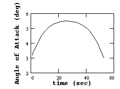
 The lift of the glider must change as it goes throught the various parts of the launch and must be larger in the middle of the launch than at the beginning or end. Since the lift varies as the square of the velocity and the velocity is constant, the only other method of increasing lift is to increase the angle of attack. The graph below shows the angle of attack for the Ka8 during the launch.